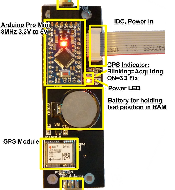
The GPS Referenced RF Generator product is a RF generator with the following characteristics:
-
Outputs a RF signal that is locked to the GPS network.
-
Is useful for frequency calibration.
-
Powered from a IDC connector using 3.3V to 5V.
Data:
-
Frequency:
0 to 10Mhz in 1 Hz steps -
Size:
100x33,3mm PCB. -
Power usage:
Circa 0.5W. Can be powered from 3.3V to 5V DC
Theory of operation:
The GPS RF Signal generator is an Ublox NEo-6 GPS module that is controlled by an Arduino Mini Pro 8MHz.
When the Neo-6 module gets a GPS position fix it will output a RF signal on its RF output.
This signal is referenced to the GPS network and thus can be used a calibration source.
The frequency to be output is set by the on-board Arduino.
The user will communicate with the Arduino using a serial command structure. The commands will be translated and converted to the Ublox specific API.
This hides the complexity of the GPS programming and enables easy to use serial commands for frequency programming the Neo-6 module.
The programming can be saved in the Arduino EEPROM and be automatically used after power up.
Operation.
To operate the GPS Referenced RF Generator do the following:
-
Connect an active or passive GPS antenna to the GPS SMA input connctor. The module will power an active antenna on this port. The voltage presented is the Voltage used to power the device thru an 10ohms resistor.
-
Connect power on the IDC connector. Valid input voltage is 3.3 to 5V. The module will need about 100mA.
-
Optionally connect the serial lines to a PC or to electronics that will send serial commands to it.

Monitoring the device.
Status LED
The device can be monitored on the the yellow status LED or on the serial port.
If the yellow LED is off it indicates a hardware error. In that case connect to the serial port and read the status messages for more information. The most likely reason is a defective GPS module or voltage regulator.
A blinking LED indicates that the GPS is working and waiting for a GPS fix.
A steady lit LED indicates it has acquired a fix and is outputting RF signal on the RF connector.
Serial Port
The Serial port puts out status messages and can accept a few commands to control the device.
A typical boot message will look something like this:
Zachtek GPS referenced RF, Software version: 1.06
Blinking Lock LED
Turning on Voltage Regulator for GPS module
No startup frequency data was found, using 1MHz
Programming GPS
GPS Initialized to output RF at 1000000Hz
Initialization is complete.
Type one of the following serial commands to control the GPS Module:
: F ... ,(FREQUENCY) sets a new output frequency, value in Hz or use k or M suffix for kHz and MHz
: S ,(SAVE) Saves the current frequency to be used as startup frequency
: P ,(PASSTHROUGH) Enters passtrough mode, GPS serial data will be passed to and from this Serial port. Reset the module to go back to normal mode
: H ,(HELP) prints this information
Waiting for GPS location fix, RF turned OFF
At this stage the Yellow LED will blink to indicate that it is waiting for a GPS position lock.
Once it has a position the the yellow LED will be constantly lit and the serial port will output :
Fix acquired, RF turned ON. (Location is: xx.xxxxxx,xx.xxxxxx)
IDC Connector
Pin 9 on the IDC connector functions as a GPS lock indicator
It is kept low while the GPS is acquiring a location fix and goes high once it has a location fix.
Pin 10 is connected to the RF Output.
Configuring the device.
Serial Port
To change the frequency on the RF port use the "F" command on the serial port followed by the frequency in Hertz or use a prefix like k for kiloHertz or M for MegaHertz.
E.g. "F 2M" will program the output to 2Mhz.
The device will respond with :
GPS reprogrammed to output RF at 2000000Hz
To save the current frequency to be used at startup issue the command "S". The device will respond with:
Frequency was saved
The GPS has a special Pass-trough mode that can be entered by issuing the serial command "P"
After this command has been received the device will relay all the GPS Serial data out on the serial port.
This makes it possible to gain direct access to the GPS.
This is useful if one wants to use a software like U-Center to program and monitor the GPS.
After the "S" command has been received the device will answer:
Entering passthrough mode -- reset microcontroller to return to normal mode
The device will then be outputting serial data in a steady stream from the GPS and the serial commands will be disabled. Any data sent to the device will now be passed to the GPS module instead of being parsed by the serial command engine.
To abort pass-trough mode reset the Arduino or remove power.
The serial data will look something like this and will continue to be streamed out until the Arduino is reset:
$GPRMC,111644.00,A,5615.63593,N,01234.45568,E,0.099,,150818,,,A*71
$GPVTG,,T,,M,0.099,N,0.184,K,A*2E
$GPGGA,111644.00,5615.63593,N,01234.45568,E,1,11,0.82,38.6,M,38.8,M,,*6C
$GPGSA,A,3,27,20,16,21,10,08,26,15,07,13,30,,1.59,0.82,1.37*0C
$GPGSV,4,1,13,04,11,173,27,07,16,309,43,08,35,291,43,10,44,157,35*70
$GPGSV,4,2,13,13,12,024,12,15,18,061,27,16,45,200,40,18,03,247,*7D
$GPGSV,4,3,13,20,57,114,26,21,45,076,32,26,20,183,28,27,72,278,43*72
$GPGSV,4,4,13,30,10,338,25*46
$GPGLL,5615.63593,N,01234.45568,E,111644.00,A,A*6D
$GPRMC,111645.00,A,5615.63594,N,01234.45564,E,0.104,,150818,,,A*7E
............
IDC Connector
If the I2C pins 7 and 8 on the IDC connector are shorted at startup the device will enter pass-trough mode and stay in this mode until the short is removed and the Arduino is reset.


